🛠️ Project Overview
This coursework focused on building a real-time position control system using a cart on rails, an ultrasonic sensor, an Arduino microcontroller, and an RC servomotor. The project challenged me to model physical dynamics, tune controllers, and optimise system response through simulation and hands-on testing.
🎯 Objectives
- Design a stable closed-loop control system
- Model physical dynamics with Newton’s laws
- Calibrate sensor data and apply digital filtering
- Tune PD and PID controller gains for fast, stable response
- Test system under real-world constraints
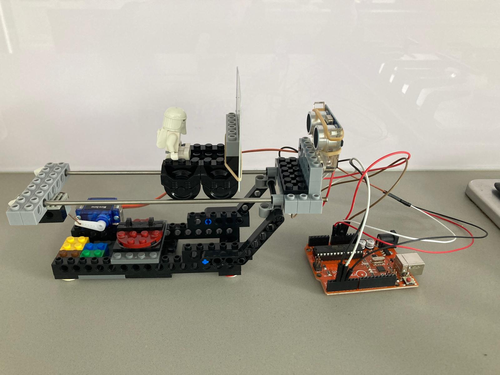
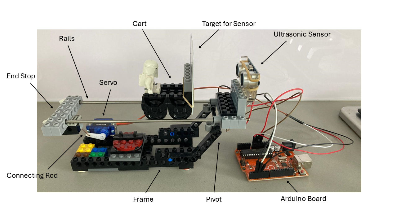
🧪 System Overview
The mechanical setup included a cart rolling along rails, with distance measured by an ultrasonic sensor. A servo motor adjusted the tilt of the rails, thereby controlling the cart’s position.
Mechanical Improvements:
- Repositioned centre of mass with added rear weight
- Blue tack used to dampen vibration
- Rails and sensor were constrained to prevent drift
- WD40 applied to minimise friction in wheels
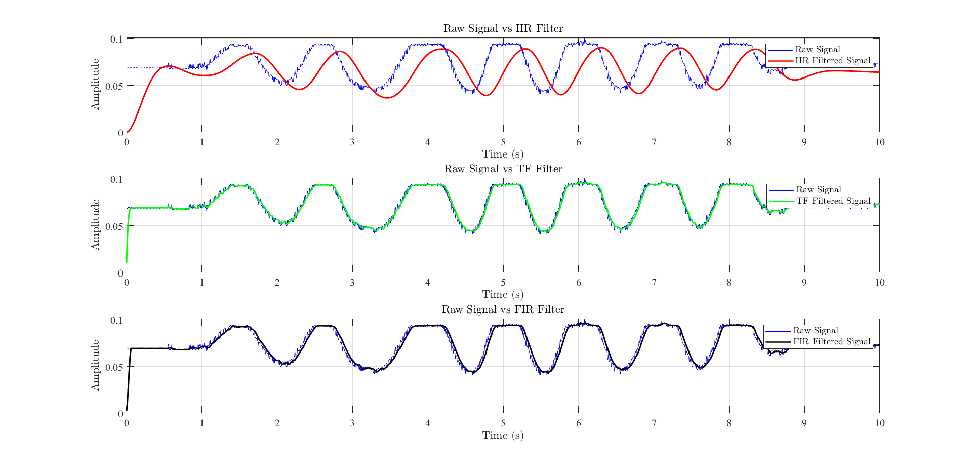
📐 Calibration and Filtering
Sensor calibration revealed a signal offset of 2.1 mm and gain of 1.032.
A Fast Fourier Transform helped select a 20 Hz cut-off frequency, and multiple filters were compared:
- Analytical
- IIR (Chebyshev) – high phase lag
- FIR (Kaiser) – best performance, minimal lag
⚙️ Modelling and Controller Design
Using Newton’s second law and the small-angle approximation, I derived a transfer function linking rail angle to cart position. A PD controller was initially designed with:
- Proportional gain = 2.24
- Derivative gain = 0.668
These values were simulated and later tuned based on real-world constraints including servo response time, physical rail limits, and sensor phase lag.
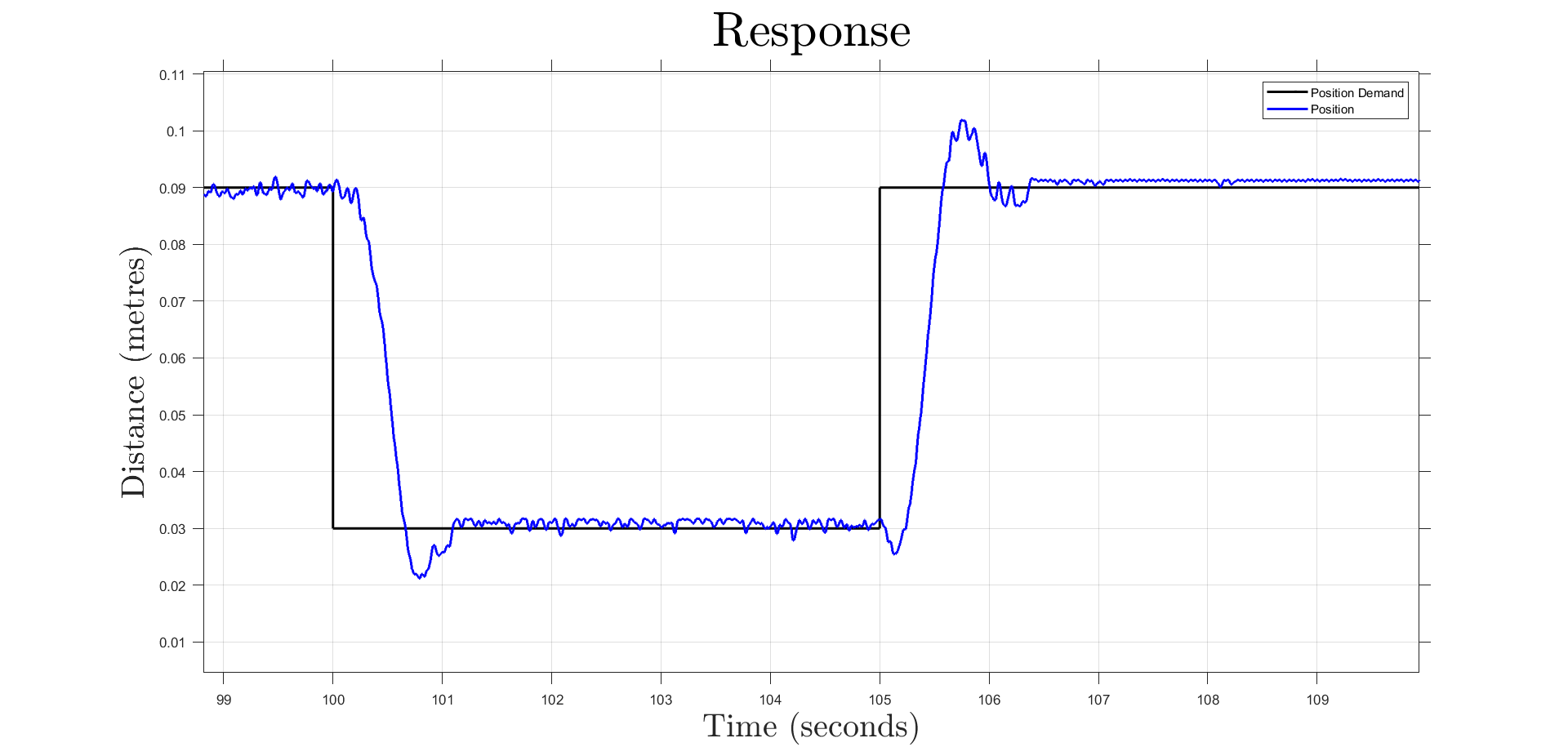
💻 Simulation and Testing
A Simulink environment was used to assess controller performance with real-world imperfections. After multiple iterations, the final tuned PID gains were:
- P = 6
- I = 1
- D = 1.6
Final system performance:
- Rise time: 1.05 s
- Overshoot: 13.3%
- Steady-state error: 0.003 m
- Gain margin: 29 dB
- Phase margin: 75°
📘 Technical Highlights
💬 Final Thoughts
This project deepened my understanding of practical control engineering — from modelling and signal filtering to real-time tuning. It was a rewarding hands-on application of theory, and it gave me valuable experience using MATLAB, Simulink, and embedded systems to deliver precise, stable system behaviour.